Weld Tooling Design Company Introduces New Cost Saving Clamp Risers


Lean Manufacturers Discover Time and Cost Savings in Their Product-Holding Fixtures With Clamp Risers by Rentapen

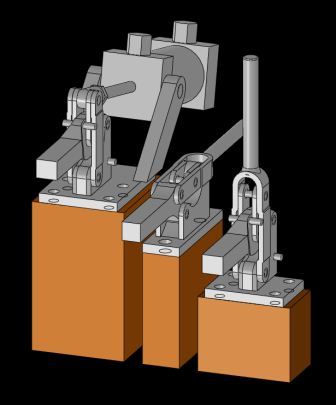
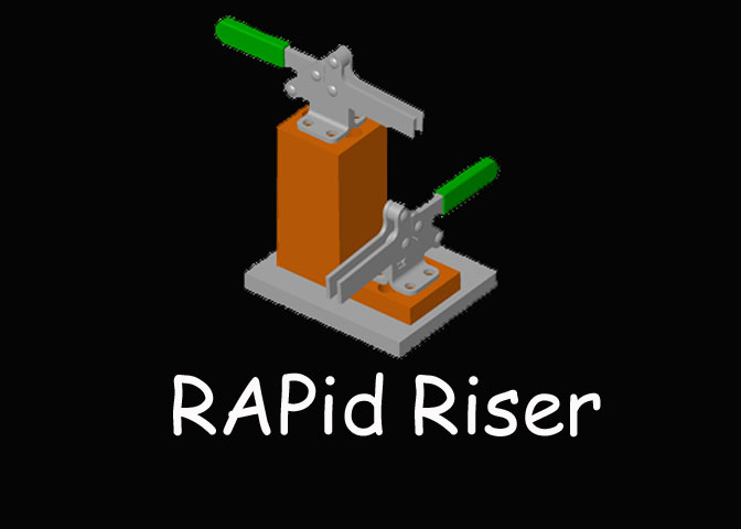
In the beginning of April, 2013 Rentapen Inc. launched new website pages for their line of clamp risers and spacers.  The clamp risers are made specifically for different brands of clamps including: Wolverine, Carr Lane, REID, De-Sta-Co, TE-CO, All American, and Jergens.   Each riser or spacer is tapped and drilled for mounting the designated clamp and uses counter bored holes for mounting the riser or spacer to the fixture or jig.

Rentapen’s design team has been designing and building weld fixtures for over 35 years. They realized they were designing the same clamp risers over and over again.  So Rentapen developed what is now called RAPid Risers™,  a line of tooling components that hold all of the finest brands of part holding clamps.  These standardized yet versatile risers save manufacturers time and money when it comes to the design and build process.

Wolverine Clamps3D CAD Models of the risers can be downloaded from Rentapen’s website along with informational PDFs that detail the design of the RAPid Riser™.

 “By focusing our processes and skilled talent on what we do well, we free-up our customers time, energy, and talent to be more powerful and productive with what they do well,” said Susan Straley,  President of Rentapen.  “That gives them peace of mind and contributes to their success.”

If a designer created a clamp riser from scratch, like Rentapen and all other machine tooling design companies used to do, they would have to go through a timely and expensive process that includes: designing the part; detailing; checking; ordering material; writing the CNC code; creating the part and finally inspecting the part.

This entire process takes about 77 minutes. Manufacturers are now able to download the 3D model from Rentapen’s website, save the model to their library, put the riser into their design, and order the block.   Once the model is in the company’s CAD library, the process approximately takes 4 minutes.  Rentapen’s RAPid Riser™ is saving the manufacturers as much as 73 minutes in design and build time.

 “The RAPid Risers™ are just another way for the fixture builder to save time and money on the design and build of weld fixtures or any other type of fixture,” said, Steve Pautz, Product manager at E.L. Simeth Co. a distributor of the clamp risers.  “The Clamp Risers is just one part of this unique design system that really works. E.L. Simeth Company, as the distributor for this line, has customers that use the complete line so we know that it works very well,”

RapidRisersRapid Tooling Components™ reduce the design cost of the fixture by eliminating the need to design, detail and check similar parts over and over again. Three dimensional computer models are provided by Rentapen Inc. that customers can use to incorporate into their designs.  These modular components are the new standard in weld jig and assembly fixture design.

Rentapen Inc., is the weld fixture specialist, and is home of RAPid Tooling Components. Rentapen Inc. has been providing machine tool design services to manufactures since 1976.  A Certified Woman Owned Business and owns RAPid Tooling Components™. For more information about Rentapen Inc., please call 262-542-8891.

3D Models of Tooling Components Assists in Growth of Weld Fixture Design Company As New Part-Holding Tooling Pieces are Added.


Rentapen Inc., of Waukesha, WI, Continues to Expand the Number of Components and Product Parts Available for 3D-Model Download.

In January and March 2013, Rentapen Inc., a 3D CAD Design Company added several new components to its 3D-Model download web page, www.WeldFixtureComponents.com.

Rentapen Inc., offers a large custom line of RAPid Tooling Components™ that can be downloaded for free to help manufactures save time and money while designing and building their weld and assembly jigs and fixtures.  RAPid Tooling Components™ are a new American standard for the machine design Industry.

An alternative to NAAMS, Rentapen’s components along with the 3D models have changed how Machine Design Engineers and CAD Drafters design their weld fixtures.

 “In 2001 we discovered we, as weld fixture and assembly fixture designers, were designing the same parts over and over again.  So we realized if we standardized on those parts we could save our customers lots of time and costs.  So we created RAPid Tooling Components™,” said George Straley, Founder of Rentapen.

Rentapen Inc., has a total of 9 different types of RAPid Blocks™ that can be ordered to fit different tooling fixture needs.  In the beginning, customers would buy the RAPid Block™ and then if the block needed to be altered, they would place the part in their CNC or take it to another vendor. RAPid Blocks are often altered to add a hole in it to hold a locating pin or a rest pad or to chamfer a corner.   In 2011, Rentapen Inc., began to offer customized alterations to their RAPid Blocks™.

Rentapen Inc., manufactures each block as it is ordered.  This allows them to keep inventory low and provide a valuable service to their customers.  Rentapen Inc., will customize the RAPid Block™ per the customer’s specifications. “Need a chamfer? No Problem.  Need a hole for a locating pin?  No problem,” said Susan Straley, President of Rentapen.

Productuon Part Holding MachineryAll of Rentapen’s RAPid Tooling Components™ are made in the U.S.A. This is in line with Rentapen’s vision as the U.S. Leader in machine design and tooling components.  Rentapen is dedicated to reducing costs for manufacturers. And their free 3D service is greatly help manufacturers on their lean journey.

Rentapen Inc., is the weld fixture specialist, and is home of RAPid Tooling Component™s. Rentapen Inc. has been providing machine tool design services to manufactures since 1976.  A Certified Woman Owned Business and owns RAPid Tooling Components™. For more information Rentapen Inc., please call 262-542-8891 or visit http://www.rentapen.com.


Weld Fixture Design 101 Posts A New Blog To Educate Manufactures and Engineers


Rentapen Inc.’s President, Susan Straley, Educates The
Engineering Industry With Her Weld Fixture Design Blogs.

On February 25, 2013, Susan Straley posted her latest blog educating the engineering industry about an easy and practical way to determine fastener length. Susan Straley, known as the Queen of Lean Machine Design and President of Rentapen Inc., has been educating the manufacturing and engineering industry about weld fixture designs since October 2011. Her blog is called Weld Fixture Design 101. The lessons are being published as often as every two weeks.

The Weld Fixture Design Blog informs the audience on how to design a simple weld fixture, the use of their RAPid Tooling Components™, and trends in the many different outlets in the manufacturing industry.  The Blog is also designed to help Rentapen Inc., gain knowledge from their readers about what is important to them.  This helps Straley connect to her audience and potential customers.

 “I enjoy posting the blogs in machine design groups on Linkedin because there are both experienced designers and new students of engineering who participate in discussions and add their experiences and viewpoints to the mix,” said Straley.  “Then I also get ideas for future lessons.”

Rentapen Inc., has been active in the hiring and training of interns from many different colleges in the Greater Milwaukee, WI area.  Along with the Weld Fixture Design 101 Blog Rentapen Inc., has created a series of videos and instructions that have incorporated what Straley has written about in her blogs.

Design Fixtures and Jigs using Pro/E and Solidworks

 “I remember when I was just starting out as a CAD Drafter.  There was so much of the practical stuff that wasn’t taught in the classroom at school,” said Straley.  “And when I learned that 40% of the Engineers in the U.S. are going to retire within 7 years, I knew I had to start sharing some of the knowledge that comes from years of doing the work.”

The Weld Fixture Design 101 Blog demonstrates how to use Rentapen’s standardized yet versatile RAPid Tooling Components™. Rentapen’s precision weld fixture components are made up of RAPid Blocks™, RAPid Shims™, Clamp Risers, RAPid Plates™, and standard shims that precisely hold your product in your weld fixture while it is being manually or robotically assembled or welded.

Subscribers to the Weld Fixture Design 101 Blog are sent notices directly to their email when a new lesson is posted.  However, the blog can also be found on the various social media sites that Straley participates.  There has been 47 different Blogs published and they cover a variety of topics from creating a tapped hole to steps to design a product-holding jig or fixture.  You can connect to Straley and Rentapen Inc., via Facebook, Twitter, Linkedin,YouTube, and many other social media platforms.

Click the link to view the latest YouTube video: Easy and Practical Guide to Length of Fasteners in Machine Tool Design

Weld Fixture Design Company Engineering Manager Seeks to Grow With the Company.


Rentapen Inc.’s, Design Engineering Manager, Blake Peterson, Continues His Education To Improve Productivity.

On January 7, 2013 Blake Peterson started another fast paced group of classes toward his Bachelor of Science Degree majoring in Business Management. Peterson joined Rentapen, the Weld Fixture Specialists, in November, 2011 as Engineering Manager. Rentapen designs machine tools for companies that manufacture a product. Rentapen specializes in Weld Jigs and Shims.

The company also manufactures a line to weld tooling components called RAPid Tooling Components™. These RAPid Tooling Components™ consists of RAPid Blocks™, RAPid Plates™, Clamp Risers and Shims.

Lindsey Frick, Associated Editor for MachineDesign.com, found information from the Bureau of Labor Statistics which projects a need for 17,830 additional engineers each year for the next 10 years. Lindsey also wrote in her article that Community colleges are an untapped resource for potential engineering students.

Currently, Peterson is conducting interviews for an Engineering Project Manager that will quickly grow as Peterson grows. The Machine Designer position will involve the conception and design of weld fixtures and guiding and teaching CAD Drafters and interns as they learn.

Peterson, Engineering Manager, is expected to graduate in 2014 from Cardinal Stritch, located in the greater Milwaukee, WI area. Peterson is taking the necessary actions to get ahead in his engineering and management career. He is taking advantage of accelerated on-line classes to improve his ability to lead and expand his knowledge base. Some of the classes Peterson is looking forward to taking are Management of Leadership, Business Ethics, and Strategic Organizational Leadership.

At Rentapen Inc., Peterson is already seeking responsibilities outside the Engineering Manager title that he currently holds. He works closely with the shop to solve issues and evaluate scheduling needs. He works with the Leadership Team to expand Rentapen’s capacity to build small to medium weld jigs.

Peterson already has an extensive background of engineering management experience; however, Peterson decided to further his education in business management to understand more of the financial side of the business. The role that Peterson plays in the company, he hopes will transition from Engineering Management to more of the total Operations Management. Since joining Rentapen he has had to learn Pro/E CAD software. He has also learned each of the customers’ engineering standards to help him as he guides and checks the work of the machine designers.

Teach and Guide CAD Drafters and Interns

For the past three months Peterson has been guiding the Design Engineering Team as it focuses on reducing costs for manufacturers through lean weld fixture design. He has also been working with the Leadership Team to enhance Rentapen’s RAPid Tooling Components™. RAPid Tooling Components™ are an extension to Rentapen’s mission to save manufacturers time.

The role that Peterson is aiming for is to oversee the operational side of the business. He wants to move into leading the managers and participating in the planning. His new education will help him to know what to do to increase profits, increase cash, and reduce costs.

Rentapen’s Culture includes an emphasis of constant learning and self- improvement. The machine tool company’s culture statement says, “Rentapen is only as good as its team members. We aim to hire and retain the best … We are flexible. We are constantly improving ourselves and our processes. We delight in learning new skills, improving ways of doing things….”

6 Benefits to using Sub Assemblies in Machine Design

Discover How Sub Assemblies Save a Ton of Time and Money in Machine Design.

Sub Assemblies in machine design are fun and easy and the really help save time and money in a lot of ways.  Once you learn how to use them efficiently you will see all kinds of places that they can be used.  Then, you can be the CAD wizard at your company!

A sub assembly is just a 3D CAD Assembly that is inserted into the Main 3D CAD Assembly in machine design.  If that sentence doesn’t make sense, keep reading and watch the video below to get a good idea of how Sub Assemblies are super tools for Machine Designers.

For example these Jergens Jig Feet along with RAPid Shims and manufactured risers are used several times in a fixture.  As sub-assemblies they save time, and unclutter the assembly drawing.


This configuration of RAPid Blocks and RAPid Shims is used in several places on a weld fixture.  Only the pin changes.


So this configuration, without the pin, is a good candidate for a sub assembly.
It will save engineering time to create it once in a Sub Assembly and then insert the Sub Assembly into the Main Assembly several times.


This goal post is part of a change over fixture.  A change over means that more than one product is welded within this fixture.  To “change over” the fixture to hold a different product, one sub assembly can be removed, and another sub assembly (or cover plate) can be put in its place.

In a fixture with lots of parts, it is easier for the machine assemblers to read the assembly drawing and assemble a machine when the drawing is less cluttered.

Benefits

1)      The Machine Assemblers will love it!  The drawings are easier to read.  There are less Balloons on the Main Assembly Drawing.

2)      It is easier to job out parts of the fixture to be made by contractors or machine shops.

3)      If sub assemblies are contracted out to be made, more people can be working to create the machine at the same time, moving the machine into production faster.

4)      Faster CAD design because the same sub assembly can be inserted several times into the main assembly.

5)      Assembly model checking time is reduced because each sub assembly only has to be checked once.

6)      The MAIN BOM can contain all the parts for the whole machine, just like always.

Numbering

It depends on your numbering system.  All parts in a sub assembly get normal part numbers.  Even the sub assembly gets a normal part number.  If a 3/8” jam nut is part 103, you can use part 103 inside a sub assembly and also elsewhere in the main assembly and it won’t be a problem.  The main Bill of Material will reflect the total quantity of parts both inside and outside the sub assembly.  And the Sub Assembly Bill of Material will contain only the quantity of part number 103 used in the Sub Assembly.

We find it helpful to use the words “sub assembly” in the name or description of the sub assemblies.  That way they are easy to identify in the BOMs.  Your company may use a special group of numbers for your sub assemblies.

Now discover how to get the Bill of Material (BOM) to show all the parts but balloon only the parts not in the sub assemblies!  Watch this short video.  (The demonstration is using Pro/E Wildfire 4.0. )

So the instructions for flattening  the Bill of Materials for the purpose of ballooning only those parts not included in the sub assembly is as follows.

Steps

  • Select Table from Top Menu
  • Select Repeat Region
  • Select Flat/Rec Item from the pop-up window
  • Select the Bill of Material (Table)
  • Select Default or Flat (to flatten the Bill of Material)
  • OR Select Recursive (to expand the BOM show the parts that are in the Sub Assemblies)
  • Select the sub assemblies in the BOM
  • Click OK or “Done”

Be sure to sign up to receive Education and Updates!  All people who sign up in April 2012 will receive RENTAPEN’s DOWEL HOLE GUIDE.

Give me a Recommendation on Linked in!

View Susan Straley's profile on LinkedIn

Leave a comment below… tell me, do you use sub assemblies?  Why or why not?

‘Til next time…

The Queen

To Drive or Not To Drive Holes in Machine Design

When do YOU Drive or Not Drive Holes in Machine Design? 

When designing a fixture it is very helpful to drive the hole in part B by using the axis of a hole in part A that is fastened to part B.  And when is “Un-driving” that hole a good idea?


When should holes be “un-driven”?

There are two times that I can think of right off the bat where a driven hole should be un-driven.  I mean “un-driven” so that the hole in Part B is no longer dependent on Part A.

1)      The machine is already built and you are making revisions.

2)      The customer requests that holes be independent of any other parts in the assembly.

 Revisions

In revisions to a machine that is already built, it is important that the CAD Drafter keep the existing holes in the same locations.  This reflects reality and if there are future revisions to the machine, the designer knows where the existing holes are.

Sometimes it turns out that those existing holes can be used in the new revision, saving machining time and costs.   But certainly the designer needs to know where existing holes are so that they don’t design in a hole that overlaps an existing hole.

When making a revision to an existing machine, if I am going to delete Part A (the driving part), I “hard-code” or “un-drive” the hole in part B first.  In this video I show how I drive and un-drive holes in Wildfire 4.0.

Please keep in mind that Rentapen has customized the process of making holes in Pro/E.  This means that your screen and hole making steps may be different than what you see in this video.


Per Customer Request

 Besides revisions, some Customers can often request that holes not be driven.  They might have had a bad experience in the past or with a different program.  In really large machine designs, the large number of driven holes can slow the CAD program down.

I feel it is a risk to not drive the holes.  If the holes are not driven and a CAD Designer makes a change to a CAD design, for example:  The Designer moves Part B but forgets to move the holes in the Part A.  The result is  a costly and time-consuming mistake.   We all know that humans are not perfect and even we CAD Drafters and Designers make mistakes sometimes.  Even if the CAD Designer remembers to move the corresponding mounting holes in Part A, if there is a typing mistake, the holes won’t match up.

Though we can hope that the person checking the changes would catch the error, it is better to make sure the mistake doesn’t happen in the first place.


Single Fastener Parts, do you drive the hole or insert the part?

Some of our customers prefer that a flat foot or anything with a single fastener not drive the hole in the part it is mounted to.  Instead they prefer that the part be located by a hard-coded hole.  They find it easier if a change needs to be made, to change the dimensions locating the hole than it is changing how the part is defined in the assembly.

For example, should this Jergens Flat Foot be located by the hole in the gold block?  Or should the Flat Foot be located in the assembly and the mounting hole be “driven” into the gold block?

Since I am a proponent of beginning with the parts that touch the product when designing, I would put the flat foot in first, complete my design, and drive the hole in the gold RAPid Block.  Then, if I am working for a customer that prefers the flat foot be located by the hole, I would un-drive the hole, re-order the parts in the model tree, and re-define the flat foot according to the customer’s desires.


So tell me, does your company have a standard on whether to drive a hole from a single fastener part?  If so, what is the standard?  Do you know the reasoning behind the standard?  I would appreciate learning what you think and what your company likes.

‘Til next time!

Susan Straley
Queen of Lean Machine Design

Remember!  Sign up for Education and Updates on the Rentapen website in April 2012 and receive a free Dowel Hole Guide for your desk top!


What Where and How of Metal Shims

What, Where, and How of Shims and Shim Packs

I am excited about our new Free 3D CAD Models ordering service on Rentapen’s web site.  I know I promised to talk more about the simple weld fixture (weld jig), this week,  however I am delaying that because this is (I think) so COOL!!

Our line of tooling components are now even easier to use.   I invite you to play with this new 3d model downloading service.  These files are Free!  Since we are still discovering kinks, be sure to let us know if you find any problems.

The videos I have for you today are about how to use this service.  But there is so much more to learn. These videos aren’t polished, but you will get the idea.

First, I talk about shims and show how they are placed in a real fixture. You might want to turn the volume down a bit, I start in the shop…

I know I go on and on about shims at times. I am a big advocate for shimming in weld fixtures.

With so many variables involved in how much heat will be created during welding and therefore, how much distorting will occur on the product being welded, shims and shim packs are essential. They help the production group set up the fixture before full production begins. So that when the weld jig or fixture goes into full production it is putting out a product that works.

In this next video I  show you how to download a file for a RAPid Block(TM) and a RAPid Riser(TM).

And in THIS video, our team member, Kory, tells you how to get your Pro/E parameters into your STEP file.


I hope you have fun trying out the new 3d models and seeing how you can use them. I’d love to see what you come up with! Didn’t you like playing with legos??

Send images of your designs using RAPid Tooling Components to news@rentapen.com

The Queen of Lean Machine Design


The Diamond Pin, The Shoulder Screw, and The Bushing-Weld Fixture Design Lesson

Now that we have a Diamond Pin that is only touching the part on the top and the bottom of the pin, we need to make the contact points of the pin remain in the same up and down orientation.

To say it differently, we have to make sure the diamond pin doesn’t rotate.  We can do this with a flat cut on the pin and a shoulder screw mounted next to the cut.  Let’s take a look at the video…


Thanks for joining me as we learn together. I hope you are having as much fun learning as I am!

Next week we will talk about how this sub assembly is shimmed and mounted.

The Queen of Lean Machine Design

Jig or Weld Fixture Design — Holes 101

In machine design there are fundamental rules to follow when locating fasteners.  I remember taking drafting classes but I was taught the basics of holes and hole locating only after I started working for Rentapen many years ago.

Mr. Iyer commented on the blog last time that I didn’t talk about construction holes for locating the angled cut on the v-block. He is right! So this video talks construction holes. I just want to add that in the video I put in .313″ construction hole. Looking back at it, a .25″ would have been better for this small part.

Also the video today talks about a major rule of thumb for locating mounting holes.

Mr. Iyer’s comment talked about using a plane that goes from the construction hole to the dowel hole that was zero/zero in the other surface. If this helps, where should I locate the other zero that is normal to that one. Also at the original surface dowel?

Remember, nothing is written in stone here. So if you know a better way or your company does it differently, share that with us in the comment section below!   Are there other rules of thumb you can share?

MORE TO LEARN!

A reader of this blog, Marvin Davis, has shared with us some links to other free education.  It doesn’t appear that any of them are on machine design, but some are on computers and math and so might be of interest to you.  I am sharing the list below.  But before you leave us to surf and learn, be sure to sign up for Rentapen news and updates on the right side of this page.  Then you will be notified of the next Weld Fixture Design 101 blog.


The Really Free Schools are Onlinehttp://www.independent.co.uk/life-style/gadgets-and-tech/features/the-really-free-schools-are-online-2353052.html


Berkeley Webcasts

http://webcast.berkeley.edu/series#c,s


CERN Document Server

http://cdsweb.cern.ch/


Harvard Open Learning Initiative

http://www.extension.harvard.edu/open-learning-initiative


Houston – University of Houston

http://www.youtube.com/user/UHouston#g/c/4F8EC29025F10C20


Indiana Multimedia Distribution System

http://www.imds.iu.edu


iTunes U

http://www.apple.com/education/itunes-u/


Khan Academy

http://www.khanacademy.org/


Math On Line – University of Colorado Colorado Springs

http://www.uccs.edu/~math/vidarchive.html


Mathematical Sciences Research Institute

http://www.msri.org/web/msri/home


MIT Open Course Ware

http://ocw.mit.edu


McGill Courses On Line

http://cool.mcgill.ca/


nanoHUB

http://nanohub.org/


Open Learn – the Open University

http://www.open.ac.uk/openlearn/


Oxford Podcasts

http://podcasts.ox.ac.uk/


RSA Animate

http://comment.rsablogs.org.uk/videos/


Scribd – Social Publishing

http://www.scribd.com/


Stanford Engineering Everywhere

http://see.stanford.edu/see/courses.aspx


Video Lectures

http://videolectures.net/


Yale – Open Courses

http://oyc.yale.edu


YouTube – Education

http://www.youtube.com/education


Jig or Weld Fixture Design — Five Items to Consider in V-Block Design

Five items to consider when designing your V-block

In our last Jig or Weld Fixture Design blog we talked about different ways to locate a round rod or tube.   One of the more common ways is with a v-block.

Today we will discuss some of the questions that help you decide the material, modeling method using Pro/E  4.0, and fastener locations.

1)      MATERIAL  —

First decide what material you will need the v-block to be.

How much will the fixture be used?    That means knowing what the product is made of because we need the v-block to be strong enough not to wear down too quickly.  We want to be able to produce lots of product before we have to replace any of the parts in the fixture.    The more the fixture is going to be used the harder you need to make the v-block relative to the product tube or rod.

Do you need to plan for weld splatter?

If the v-block is located near the weld joint, you will need to consider using a metal that the weld splatter will not stick to as easily, or using a weld splatter shield.  Remember that like metals stick better.  So if you are welding steel, you may want your v-block to be Ampco 18 bronze or a hardened steel such as 4140 PH or A2.   If you are welding aluminum, hardened steel may work just fine.

2)      TOLERANCING –

Is the location of the rod or tube critical?

If the tube or rod needs to be located in just the right spot in order to work or assemble easily to the rest of the product parts, then you will want to design in adjustability with shim packs.  You will need to look at the product drawing and also know your customer’s preferences.

At Rentapen we design for many different customers.  So we have to consider the standards and preferences of each customer when we design.  Some of them love to shim every locator in a fixture.  Some of them don’t like to shim at all.   If you are a CAD drafter, you may be working under more than one designer.  Each designer may have their own preferences.  But it is up to you to look at the product drawing and then advise them when you think shims will be needed to meet the tolerances of the product drawing.   Then do what they say, they are your customer.

If it is a rough location, you may be able to use a purchased V-block from somewhere.  Do you have a favorite model or brand you would like to share?

3)      FASTENERS –

Once you have decided if your v-block will have shims to fine-tune its location before going into production, you can decide about the location of the fasteners.  If the tube or rod location is critical, you will need to use dowels to lock in the location.  If it is rough, you can just fasten the v-block directly to the base plate with screws.

4)      MODELING —

Locating the Vee in the v-block.

Here is how I model in the Vee cut.  Click on the video to see my method using Pro/E  Wildfire 4.0.

In this video I dimensioned the construction hole from the BOTTOM of the block.  However, the v-cut may fail if I make an adjustment too big in one direction or the other.  Some of the project engineers I have worked with prefer that the dimension for the V-cut be from the TOP surface of the block.  That way you can change the size of the block without having problems with the cut.

Some like to create planes that intersect at the center where the the construction circle will be located.  These planes are created before you start the sketch to cut the Vee.  I think your preference depends on your experience and how your brain works when making adjustments to parts while in the assembly.

5)      CLAMPING —

Clamping is a whole topic by itself that we will address in a future blog.  I just wanted to note that it is something that you need to think about.  We always clamp down our parts in weld fixtures, even if it is a table mounted fixture and gravity does its work.  You want to be sure that tube doesn’t move when the heat of the weld hits it.


And now I would like to share a couple of things with you.

First, Rentapen’s Holiday Greeting to our customers, vendors, students, and friends.

Second, we are in the news!  Check out the latest news at Rentapen by clicking here.

Till next time!

Susan Straley

The Queen of Lean Machine Design