


WELD FIXTURE SPECIALISTS ANSWER NEED TO MAKE WORK HOLDING FIXTURES EASIER TO CHANGE
Protective brass caps for fasteners help manufacturers re-use components and make changes to machine tools.
 THE RAPid CAP STORY
In 2013, George and I were sitting in the long, grey conference room with our customer. He was complaining, “The problem is, when I want to make changes to the weld fixture, it’s a real pain because the fasteners are all full of weld spatter. We can’t get at the socket to remove the screw.”
This sounded a bit familiar. Sometimes it takes hearing a thing more than once for it to sink through our thick skulls. At that moment, we realized that this was an issue with most of our customers that did welding to produce their end product. George and I looked at each other. “What if we made something to protect the screws from splatter,” I asked. “Would that make it easier for you to use and re-use our RAPid Tooling Components?”
“Sure!” he said. “When I was done with a fixture I could re-use the components if I want to… or even to add an adjustment shim if we need to.”
George is good at coming up with great designs. He and his team were behind the idea of RAPid Tooling Components back in 2000. So I let him stew on it. I told him that once he got a few made we needed to send them into the real world to be tested.
It didn’t take him long to come up with a design for RAPid Caps.
So we sent some out to our customers to try on their fixtures. The feedback was terrific and orders came in before we were set up to market them. RAPid Caps obviously fill a need in the welding and weld fixture world.
Susan Straley
Queen of Lean Machine Design
Rentapen Inc.
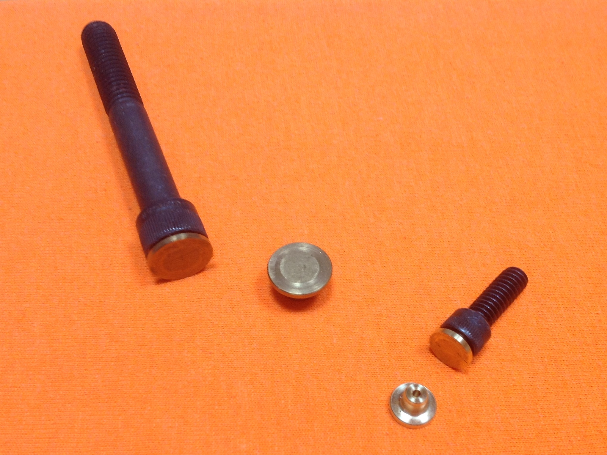
WHAT ARE THEY?
RAPid Caps are made of brass. A round stem presses into the socket of a socket head cap screw and covers the top of the screw leaving a slight gap between the head of the screw and the RAPid cap.
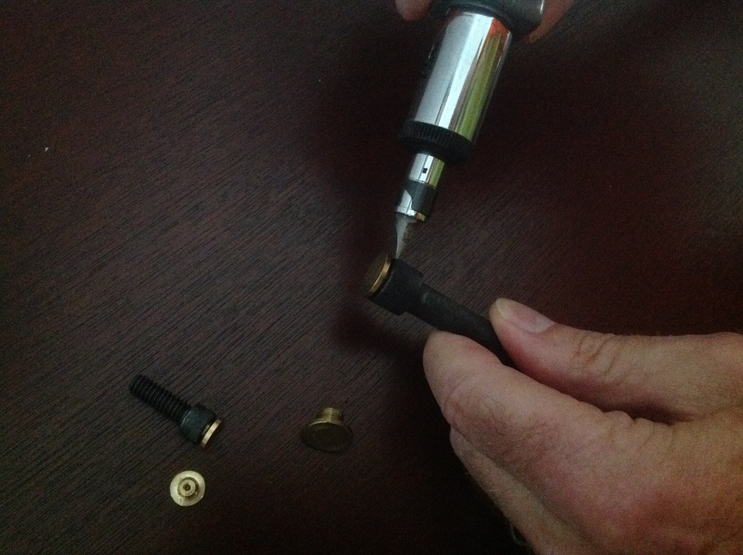 The tip of a screw driver is wedged into the gap and pops the cap off.
Adjustments and changes can be made. And the cap can be pressed back into the socket to provide spatter protection again.
RAPid Caps come in inch and metric sizes. Check out Rentapen’s RAPid Caps web page for sizes and ordering instructions.


